In installment 2, I spoke about matters of capacity and the roles the MNO’s BTS and the DAS have to play in this regard. I concluded with a discussion about spectrum resources, their coverage and capacity attributes and the implications for different DAS technology types. Today I will talk in more detail about DAS technologies considering the advantages and disadvantages of each. I particularly want to look at future DAS with a view to making In-Building Coverage more accessible and affordable.
There are a number of different DAS technologies available, the main candidates being Passive, Active; and Hybrid, with Digital DAS now emerging as a contender. The architectures for these technologies are illustrated in the following extract from the draft MCF 2021 DAS Specifications.
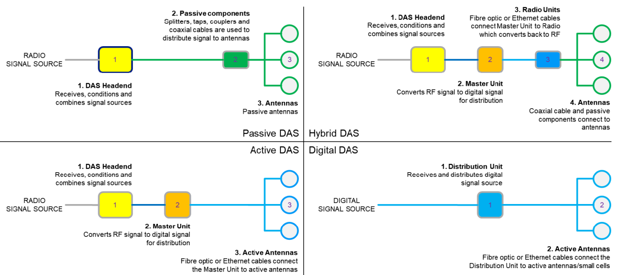
Traditional DAS types share a fundamental architectural structure. There is/are:
- A defined Point of Interconnect (PoI) with the MNO’s RAN, generally referred to as the DAS Headend;
- A distribution network connecting signals from the RAN to the antennas; and
- The antennas themselves (sometimes referred to as APs or TRPs), which serve as the network access points.
However, the key differentiators are the signal transport mechanisms, arrangement of the DAS elements in the building, and whether or not they require power.
Passive DAS

Passive DAS is currently the most common DAS technology type. Fully analogue in nature, it is composed exclusively of passive components and requires no primary power, the RF energy is provided by the RUs in the MNO’s BTS.
Today’s Passive DAS components: Antennas; Coaxial Cabling; Splitters; Combiners; Couplers are capable of supporting all low and mid frequency bands up to the latest 5G releases. So, very importantly, Passive DAS should not be dismissed or considered obsolete on the pretense the technology does not support 5G.
They are generally a low-cost option in comparison to other DAS technologies but its usage domain is usually small to medium sized buildings. Beyond this, the cost of additional MNO facilities starts to escalate.
For large buildings such as high-rise or campus environments, connectivity to antennas requires long cable runs, the loss for which ultimately leads to insufficient power for the antennas. In such cases, alternative or supplementary measures must be taken. One method is to request the MNO(s) to deploy Remote Radio Units (RRUs). RRUs extend the MNO’s RAN supporting the establishment of additional PoIs throughout the building, thereby minimising the DAS coaxial cable run lengths. However building facilities must be available for the accommodation of RRUs. This requires not only the physical space to be available but also power and environmental controls. Critically, the count of RRUs and size of the facility increases in line with the number of participating MNOs.
With the advent of MIMO, a compliant Passive DAS requires significantly more infrastructure. Even a 2×2 MIMO system doubles the cabling and components required for the signal distribution. Support for higher order MIMO (4×4) further increases the infrastructure requirement. The practicality and cost of providing multiple distribution network paths from the headend to the antennas will be significant. Other DAS technologies support MIMO in a more efficient manner. It is also important to note that not all customers require the benefits of MIMO. Hence the cost advantage of Passive DAS erodes with MIMO, and even more so in larger buildings.
While component costs are at the low-end, installation effort and cost is high especially where large diameter cabling is called for and where cabling and riser space is tight. Passive systems also involve many components and connections meaning they are highly prone to signal quality issues and installations also involve extensive testing particularly to guard against Passive Intermodulation Distortion (PIM), the bane of radio installations.
Hybrid DAS

Hybrid DAS involves all the elements of Passive DAS but also includes Active equipment.
I spoke about a major weakness of Passive DAS being the inability to provide cable reach for large buildings. The Active components in Hybrid DAS serve to overcome this problem. Instead of MNOs each installing RRUs, Hybrid DAS establishes a common set of remote RU facilities. Connection to RRUs is achieved using optical transport for the DAS backbone infrastructure. The Hybrid system takes high power RF signals from the MNO’s BTS, reduces the power to a very low level and converts them into optical signals which are then carried over optical fibre to Radio Units RRUs where they are converted back to RF. For most vendors, this carriage is a digital system (sampled RF) although it can be done as in analogue mode as Radio over Fibre carriage. Since the Headend and the RRUs need to be compatible and there is no interface standard, Hybrid systems are typically proprietary design. The RRUs which have similar power capability to the MNO’s BTS, drive the antenna segments. The Radio Units are generally modular in nature with each unit serving a particular band or band group. The RRUs accommodate the aggregate 3GPP bandwidth per frequency band meaning they support any and all MNOs. Since each RRU supports all MNOs this minimises space and power requirements where multiple MNOs are involved.
Hybrid DAS also affords for some level of DAS equipment monitoring providing for fault detection of the Active components.
In the context of medium to large buildings and in view of the full IBC solution Hybrid DAS can be more cost effective than Passive DAS when the cost of remote units and accommodation of multiple Carriers is considered.
While Hybrid DAS overcomes the line loss issues of Passive DAS, it retains the complexity and other weaknesses of the purely passive technology.
Active DAS

Active DAS involves the same Headend arrangements as Hybrid DAS. Interfacing to the MNO’s BTS, it conditions the RF signals and converts them to optical. In the Active DAS system, optical transport of the RF signal is supported all the way to the antennas where the signal is converted back to RF. Active DAS uses Active antennas which are a combination of RRUs and Antenna elements. Active DAS therefore requires a power supply at the antenna points.
Active antennas generally accommodate a number of RRUs (frequency bands) which can be tailored to MNOs (and Building Owners) requirements and readily support MIMO including limited higher order without augmentation of backbone infrastructure. Subject to defining a preferred and limited set of band and MIMO requirements, a quality DAS supporting high capacity can be provided. Under these conditions the RRU can generally be contained in a reasonably compact form factor with good aesthetics blending in with other devices and facilities present on commercial ceiling space.
Active DAS is a simpler delivery model compared with Passive systems. The significant volume of small components and multiple cable segments are replaced with modular functional elements connected by optical fibre or sometimes CAT6 Ethernet cabling. Active DAS requires greatly reduced installation and testing effort, and additionally has the capability of end-to-end real-time system monitoring.
Despite the significant advantage of Active DAS over traditional systems, Active Antennas are more expensive, especially in supporting multiple frequency bands. Hence, there is a trade-off and balancing act between reduction in installation cost and complexity vs. the added cost of Active antennas and provision of power for antennas.
Based on OneWiFi’s design and modelling and in alignment with the draft MCF 2021 DAS specifications, Active DAS can be more cost-effective than Passive or Hybrid DAS for larger buildings, however given the current price point it is still not a viable option for smaller implementations. Increased adoption of Active DAS equipment will drive the cost down, providing the potential of widening the market.
Digital DAS

All the DAS technology types presented so far involve carriage of high-power analogue RF signals generated by a MNO’s BTS. This requires the presence of MNO BTS and supporting equipment onsite. In addition, each MNO provisions and operates a separate transmission, which adds up to quite a significant infrastructure footprint and cost especially when multiple MNOs are present.
Digital DAS, which the MCF DAS 2021 Specifications briefly touched on, represents a significant evolutionary point for DAS technology. A Digital DAS supports the transport of digital signals with the conversion to RF occurring only at the Active Antennas, the final point in the chain.
The significant leap forward here is the elimination of MNO infrastructure presence onsite, seamless integration with the DAS and with the use of Active DAS technology, hence simplified in-building infrastructure. It also allows the potential of using a single transmission link to support all MNOs to achieve significant cost savings.
In a Digital DAS, signals from a MNO’s Baseband Unit (BBU) or Distribution Unit (DU) are fed to RRUs (Active Antennas) via an optical fibre connectivity network. This is the same arrangement used on Macro sites. The interface is facilitated using a specification called CPRI (Common Public Radio interface). Unfortunately, the CPRI specification allows room for specific parameter configurations which has created a vendor proprietary environment. However, the advent of virtualised RAN and particularly Open RAN, which at its heart, seeks open and compatible equipment interfacing is an avenue to overcome proprietary solutions. Several Open RAN equipment suppliers have integrated RAN-DAS solutions available today.
Virtual DAS
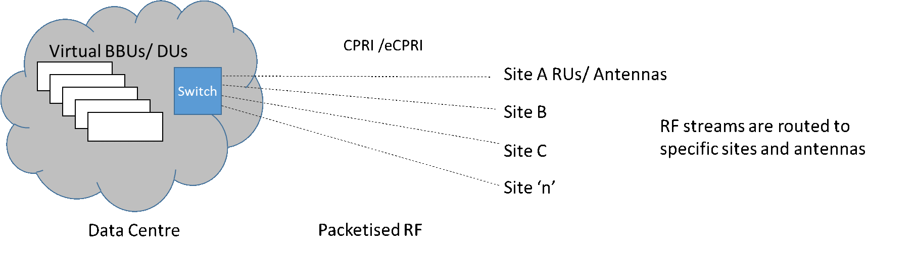
Finally, the introduction of Digital DAS also heralds a rethink of the demarcation of the RAN to DAS connectivity towards consideration of an integrated RAN/DAS infrastructure especially under a service arrangement which could be provided by a third party under a Neutral Host supply agreement. Such a facility would see the establishment of a data stream as the Point of Interconnect (PoI) for each MNO which would typically be located at a Data Centre.
Taking this further the concept can be extended to consideration of a Virtual DAS involving the establishment of private Cloud RAN environments where packets signals are switched to appropriate sites and antenna locations. This would enable a cluster of virtualised BBU/DU to service multiple buildings to drive further cost savings beyond consolidation of onsite infrastructure and transmission, potentially enabling a scalable Neutral Host model.
Coming back down to earth, all these ideas and development is about making In-Building Coverage more available and affordable, overcoming barriers to entry for Building Owners. Moreover, for the environment it’s about becoming less wasteful and more efficient in our usage of energy. The OneWiFi team are very excited to be at the forefront of driving change in making Digital DAS and Virtual DAS a near-term reality.